AIR BREAK SYSTEM
Introduction
During monoplace hyperbaric oxygen therapy, it is necessary to provide an alternative air breathing source. This may also be necessary to reduce the risk of central nervous system oxygen toxicity.
Description
The air breathing system consists of an independent high-pressure air source, capable of providing flow that is sufficient to meet the patient's inspiratory demand. Air breathing systems may be provided by institutional gas outlet (wall outlet) or via portable "H" cylinders utilizing a diameter index safety system (DISS) regulator. Delivery of the air break to the patient may be provided by disposable non-rebreather mask, demand valve and resuscitation mask or trach collar. For purposes of infection control, masks should be single patient use and cleaned or replaced (per patient) as needed.
Equipment Set-up
- Confirm medical grade compressed air H cylinder, high-pressure reducing regulator (set at 70 psig) or wall gas source is properly connected to the external chamber door (DISS or flowmeter).
- Connect the Non-rebreather, demand valve with mask or trach collar to internal gas outlet via DISS or christmas tree adapter.
- Confirm gas source pressure is set at 70 psig and test the system prior to initiating compression.
- H cylinders should be turned completely open during treatment.
- Instruct the patient about the rationale for the air break process.
- Confirm the patients understanding of how to use the air break delivery device.
Procedure
All patients treated in the monoplace hyperbaric chamber will have with the capability of administering an "air break" at any point during his/her treatment.
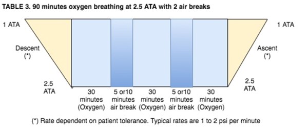
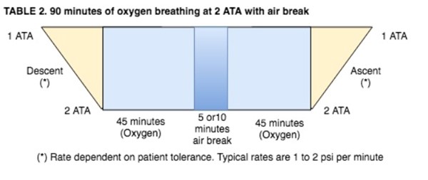
- Patients being treated at pressures above 2.0 ATA breathing 100% oxygen will receive scheduled "air breaks" as follows:
- Patients that are known to have increased potential for central nervous system (CNS) oxygen toxicity and every patient being treated at pressures above 2.0 ATA will be given an "air break". Conditions that may increase the potential for CNS oxygen toxicity are:
- Febrile state (oral temperature >100˚F)
- Seizure history
- Associated head injury
- Concurrent administration of medication known to lower seizure thresholds
- This air break should be delivered as follows:
NOTES:
- For any CNS complications that develop during a patient's HBO procedure, refer to the "Oxygen Toxicity Emergency Procedure".
GAS CYLINDER
The following guidelines should be followed for storage, transport, and use of compressed gases in accordance with all federal and local regulations.
Safety Precautions
- Ensure correct gas cylinder by correctly identifying the cylinder label, color code. Analyze and document FI02. Labels shall not be defaced, altered or removed.
- Observe safe handling and storage regulations.
- Never attempt to mix gases in cylinders or transfer gas from one cylinder to another.
- Never allow hands, gloves or other clothing contaminated with oil or grease to come in contact with the cylinder, regulator, valve, gauge or fittings.
- Never use the cylinder for any purpose other than to deliver the specified gas.
- Always use the proper connections to fit the cylinder valve; do not improvise.
- Never allow cylinders to be dropped or strike each other violently. Under no circumstances should cylinders be used as rollers or supports. Never attempt to pick up a cylinder by the valve cap.
- Ensure the cylinder opening is clean and free of debris prior to attaching the pressure regulator.
- Attach pressure regulator and check proper function.
- Attach flow device to regulator and to patient.
- Review safety regulations with patient or caregiver if appropriate.
- Medical grade gases ONLY are to be used.
Guidelines:
- Specifically, their labels should identify cylinder gases. Color-coding is a secondary way to identify cylinder gases. Color codes used are:
- Oxygen – Green
- Oxygen/Carbon Dioxide – Green/Gray
- Helium – Brown
- Nitrous Oxide – Blue
- Compressed Air – Black/Green or Yellow
- Nitrogen – Black
- Cylinders are to be capped and stored in the tank storage room when not in use.
- Cylinders must be chained to the wall of the tank storage room.
- Before a regulator is placed on any cylinder, full or otherwise, the cylinder would be "cracked" by slowly opening and quickly closing the cylinder valve. This prevents any dust that may have lodged in the valve opening from entering the regulator and causing a leak, or presenting fire hazard. This will also assure the staff member that the tank is not empty. The maneuver of cracking should be performed with both hands, and with the valve opening pointing away from any person.
- Pressure reducing regulators should be attached to the cylinder with an appropriate wrench.
- When a cylinder flowmeter is to be turned off for an hour or more, or when the regulator is to be discontinued from the cylinder, the cylinder valve should be turned off and the pressure bled from the system distal to that valve. This will prevent excessive wear on the regulator diaphragm and prolong the life of the regulator.
- Staff must be certain that the flowmeter is turned completely off when the cylinder valve is opened. Sudden high pressure on such open system is the most frequent cause of regulator damage.
- The cylinder valve should always be opened slowly and completely with a regulator is in place. Opening of this valve too quickly admits too much pressure too suddenly on the mechanism and is a frequently cause of regulator damage.
- When a cylinder is in use, it must be secured by one of the following means:
- Chained to a carrier with all carrier wheels resting on the floor.
- Screwed securely into a ring stand.
- Placed on a cart that has specifically designed tank carrier.
- No cylinder shall be transported through the halls without the use of a carrier designed for that purpose.
- All cylinders used for the administration of continuous oxygen should be promptly replaced when the pressure falls below 500 psig.
- When E cylinders are changed, staff must see that the sealing washer (provided with each new E cylinder) is properly placed. Do not over tighten.
- Safety Systems
- Pin Index Safety System prevents accidental interchanging if regulators with inappropriate E (or smaller) cylinders due to pins on the regulator yoke and holes drilled in the cylinder valve.
- Diameter Index Safety System (DISS) prevents accidental interchanging of regulators with inappropriate G or H cylinders due to regulator nut sizes at systems of 200 psig. or less.
- Compressed gas cylinder valve outlet and inlet connection system prevents accidental interchanging of regulators with inappropriate medical gas systems due to cylinder valve outlet sizes, and regulator nut and nipple sizes.
GROUND TESTING
NFPA 99 requires that all hyperbaric chambers are grounded and patients inside chambers filled with 100% oxygen are likewise grounded. Simple wrist continuity tests prior to each treatment can ensure this standard is met with the wrist strap and monthly chamber checks including chamber stud to wall measurements and patient ground jack to chamber stud measurements ensure ongoing continuity.
Wrist Strap
- Attach the patient ground wire to the wrist strap.
- Have patient wear wrist strap and slide stretcher with patient into chamber.
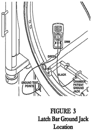
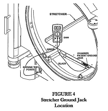
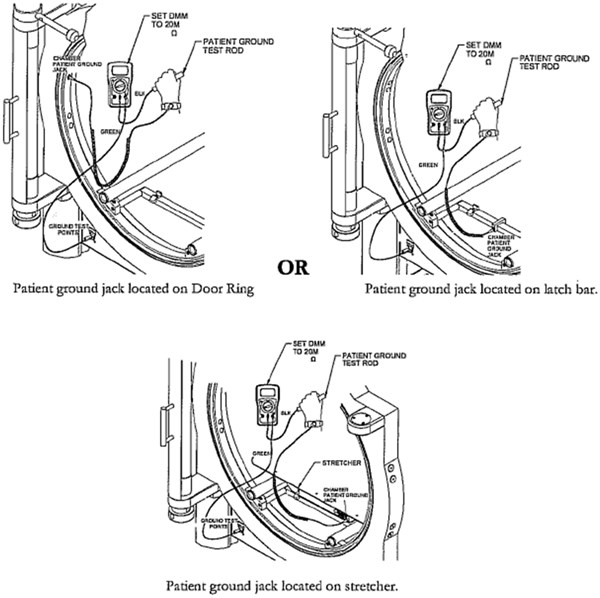
- Connect wrist strap plug to chamber patient ground jack, located on the stretcher, latch bar, or door ring (Fig. 1, 2, 3).
- Connect green test cable to the banana jack on the Wrist Strap Tester.
- Connect the other end of the green test cable to the Chamber Ground Test point jack labeled “chamber.”
- Have patient press metallic test button on the Wrist Strap Tester.
NOTE: Green light indicates continuity. Red light indicates no continuity. No continuity may be caused by dry skin, loose wrist strap or faulty patient ground wire. Try to reposition strap, moisturize skin or replace wrist ground cord.
Hyperbaric Chamber:
Chamber Stud to Wall Measurement
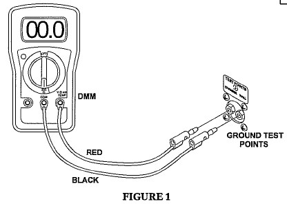
- Connect red test cable to V Ω mA jack.
- Connect black test cable to COM of the Digital Multimeter (DMM).
- Connect the other end of the red test cable to the chamber ground test point jack labeled “chamber.”
- Connect the other end of the black test cable to the chamber ground test point jack labeled “wall.”
- Turn the dial on the DMM to 200 Ohms. (Ω)
- Record the reading as shown on the LCD display
- Failure to meet this standard may be caused by dirt or film on metal stretcher wheels or axels, or dirt or film on loose connection at points of contact between rails and chamber or disconnection of chamber ground wire.
Acceptance Criteria: Reading should be between 0 and 1 Ω to meet requirements specified in NFPA99-2012 edition section 14.3.5.3.2.3
Hyperbaric Chamber:
Patient Ground Jack to Chamber Stud

- Connect green test cable to V Ω mA jack.
- Connect black test cable to COM of the DMM.
- Connect the other end of the black test cable to the chamber patient ground jack located on the stretcher, latch bar, or door ring (Fig 2, 3, 4).
- Connect the other end of the green test cable to the chamber ground test point jack labeled “chamber.”
- Turn the dial on the DMM to 200 Ohms (Ω).
- Record the reading as shown on the LCD display.
- Failure to meet this standard may be caused by dirt or film on metal stretcher wheels or axels, or dirt or film on loose connection at points of contact between rails and chamber or disconnection of chamber ground wire.
Acceptance Criteria: Reading should be between 0 and 10 Ω to meet requirements specified in NFPA77-2007 Edition Section 7.4.1.3.1
Patient Ground: Wrist Strap to Chamber
- Wear wrist strap
- Connect wrist strap plug to Chamber Patient Ground Jack
- Connect the green test cable to V•ΩmA Jack of the Sechrist provided DMM
- Connect the other end of the green test cable to the Chamber Ground Test point jack labeled Chamber
- Connect the black test cable to COM of the DMM
and the other end of the test cable to the Patient Ground Test rod.
- Set the DMM dial to 20MΩ
- Grasp the Patient Ground Test rod with the hand wearing the wrist strap.
- Obtain resistance reading from DMM display
- Acceptance Criteria: a measured value of resistance above 1 MOhms
Note if no resistance reading is obtained from DMM, the patient is not grounded.
Primary Source Sechrist Industries Monoplace Hyperbaric Chamber users Manual[1]
TRANSCUTANEOUS OXYMETRY
Goal: To ascertain suitability of selected patients to undergo hyperbaric oxygenation, and to identify a therapeutic endpoint in such patients. To determine effectiveness of hyperbaric oxygen therapy, and effective administration of air breaks in selected patients. To provide risk assessment in selected patients, pre-operatively.
Policy Elements
- A transcutaneous oximetry capability will exist in the hyperbaric treatment facility. Training in its use and application will be provided to each full-time employee through attendance of a 40 hour UHMS approved Primary Training in Hyperbaric Medicine course. Part-time employees will be in-serviced locally, and be supervised by a formally trained full-time employee. Refer to the Local Coverage Determination for Non-Invasive Vascular Testing regarding qualifications for performing TCOM
- Physicians will be trained in the interpretational aspects of transcutaneous oximetry through attendance at the above noted program, or through a similar and likewise 40 hour Undersea and Hyperbaric Medical Society approved, course.
- Patients referred with healing deficiencies, in which intact skin exists adjacent to, or is a component of the problem, will undergo a pre-treatment transcutaneous oxygen assessment unless otherwise ordered. Examples include: diabetic foot wounds, lower extremity lesions secondary to arterial insufficiency, venous stasis disease, sickle cell disease, dehisced or non-healing amputations; preparation of soft tissue defects for grafting or flap reconstruction, and late effects of radiotherapy to normal tissues.
- Transcutaneous oximetry may be incorporated into the treatment of ventilator-dependent patients. It may be incorporated into the care of other critically ill or unstable patients, on a case-by-case basis, and so ordered.
- Transcutaneous oximetry can be considered in the evaluation and risk assessment of select patients in which surgery is contemplated. Examples include: surgical procedures within or through previous radiotherapy portals, new ankle fractures in diabetics, and saphenous vein harvest sites.
- Transcutaneous oximetry can be applied in the determination of effectiveness of “air break” delivery systems.
- Site selection will be guided by the concept of transcutaneous mapping, in order to maximize interpretational potential. Sensor electrodes should be placed as close as possible to the skin margin of injury while on as healthy tissue as possible, in the evaluation of skin wounds. The radiation portal photograph, or other determination of the tissue at risk, should guide electrode placement in patients at risk for complications from radiotherapy. Skin flaps should be evaluated with several electrodes equally spaced between the proximal and distal margins.
- The informed consent process will be undertaken prior to undertaking a transcutaneous oxygen assessment.
- The testing process will be consistent with the guidelines provided in the “Chamber Operations Manual”.
TCOM Monitoring:
Measuring Site
- Optimal conditions for performing tc-P02 measurements are obtained in areas exhibiting high density of capillaries, ample capillary blood flow, thin epidermal layer and no shunting effects.
- For neonates and infants, clinical studies have shown the abdomen and chest to be appropriate measuring sites.
- For adults, clinical studies have shown the forearm, chest, shoulder and clavicle to be appropriate measuring sites.
WARNING: tc-P02 values may not reflect the arterial values in patients in a compromised hemodynamic state.
Measuring Temperature
- For neonates, an electrode temperature between 42°C and 44°C is recommended. In tests exceeding 4 hours, the electrode temperature should not be greater than 43°C in order to minimize the risk of skin burns.
- For adults, an electrode temperature of between 44°C and 45°C for tc-P02 measurements,
is recommended. In tests exceeding 4 hours, the electrode temperature should not be greater than 44°C in order to minimize the risk of skin burns.
WARNING: LONG-TERM HYPERTHERMIA MAY BLISTER SKIN
When producing local hyperaemia by means of hyperthermia, a certain risk of obtaining temperatures that are harmful to skin is always present, although this risk is limited due to the control system of the monitor modules. However, for special patients - e.g., patients in shock, patients with low blood pressure and patients with vascular constrictions, particular care should be taken whenever hyperthermia is produced.
Application of Electrodes to the Patient
In addition to the calibrated electrode, S44416 Contact Liquid and a fixation ring included in the D840 Fixation Kit are required for application.
Procedure
- Calibrate the electrode as described in Section 1. Newer TCM400 machines are self- calibrating.
- Set the alarm limits using the HIGH and LOW ALARM digital switches.
- Select a convenient measuring site on the patient and clean (de-grease) it with alcohol.
- Remove the protection film from the adhesive disc and place the fixation ring on the measuring site. Secure the center of the ring first by pressing with a finger and then secure the rim by running a finger round its circumference. Press firmly to prevent leaks.

- Apply 3-5 drops of the S44416 Contact Liquid on the skin
in the hole of the fixation ring.
- Mount the electrode on the patient. Align the arrow on the electrode just above one of the big marks on the fixation ring and then screw the electrode 1/4 turn clockwise into the fixation ring.
- Wait for a stable reading.
During in vivo monitoring, it is recommended to change the electrode site every 4 hours to minimize the risk of skin burns. Further, it is recommended to perform a one-point calibration at similar intervals.
Acoustic Alarm Cancellation
- The acoustic alarm will be activated after a 10 sec. delay when an alarm state has occurred (as indicated by a flashing display or TEMP. °C lamp).
- Pushing STOP ALARM will cancel the acoustic alarm for 3 minutes.
- The acoustic alarm will be de-activated while the electrode is situated in the electrode socket and for 3 minutes after it has been removed.
NOTE: In addition to the STOP ALARM pushbutton silencing the alarm, event marks will be made on recordings performed with TCM400 each time the button is pushed.
WARNING: If the microswitch situated in the electrode socket is accidentally activated, e.g., if an electrode is placed in the socket during in vivo monitoring, the acoustic alarm will be de-activated.
Recording with TCM400
- TCM400 TC Recorder
- Switch on the TCM400.
- Set TENSION to the required sensitivity. The HEAT DEV. range is factory preset to +100 mV, with the zero-point in the middle of the paper.
- Set CHART FEED to the required speed (2 or 12 min/cm corresponding to 30 and 5 cm/hour, respectively).
- Select the parameters to be recorded with the TENSION/HEAT DEV. switches.
- When required, switch the chart feed on with the CHART FEED START/STOP switch and check that the pens are in good working order.
NOTE: Recording of tension will be initiated when the electrode has been removed from its socket after calibration. Recording of heat deviation will be initiated when the electrode has been removed and the HEAT MODE pushbutton on the monitor module actuated in that order.
Known Interferences
- Halothane: If the patient in question is treated with the anaesthetic halothane, the operator should pay attention to the fact that halothane may interfere with the tc-Po2 electrode's reduction of oxygen and changes in skin blood flow
IMPORTANT: The use of surgical electrocautery during tc-Po2 monitoring affects the reading of results due to electromagnetic interference.
Physiological Measuring Ranges
- For neonates and infants, clinical studies have proven that tc-Pc02 reflects arterial Pc°2 within the physiological range from 20 to 80 mmHg (3 to 12 kPa).
- For adults, clinical studies have proven that tc-Pc02 reflects arterial Pc02 within the physiological range from 20 to 60 mmHg (3 to 8 kPa).
NEGATIVE PRESSURE WOUND THERAPY
To provide a process for effectively managing patients with wound V.A.C. therapy in place during hyperbaric oxygen therapy.
NOTE: V.A.C. suction will be discontinued during hyperbaric oxygen therapy.
- Prior to entering the chamber, disconnect the V.A.C. therapy unit and canister from the dressings by securing the clamps on the dressing and canister tubing. Disconnect the tubing.
- The V.A.C. electrical unit and canister must not enter the chamber.
- The drainage tube connector on the patient side should be taped and covered with gauze to contain any secretions in the tubing.
- Once the gauze is in place, unclamp the tubing to allow pressure equalization in the V.A.C. tubing and dressing.
- Place a moist 100% cotton hand towel or towel (depending upon size) over the entire dressing.
- After the hyperbaric treatment, reconnect the V.A.C. therapy unit to the drainage tubing and dressing. Turn on the V.A.C. unit.
- Confirm the dressing has no air leaks and that suction works properly. Reseal dressing, if necessary.
Official reprint from WoundReference® woundreference.com ©2026 Wound Reference, Inc. All Rights Reserved
NOTE: This is a controlled document. This document is not a substitute for proper training, experience, and exercising of professional judgment. While every effort has been made to ensure the accuracy of the contents, neither the authors nor the Wound Reference, Inc. give any guarantee as to the accuracy of the information contained in them nor accept any liability, with respect to loss, damage, injury or expense arising from any such errors or omissions in the contents of the work.